Use the correct wire
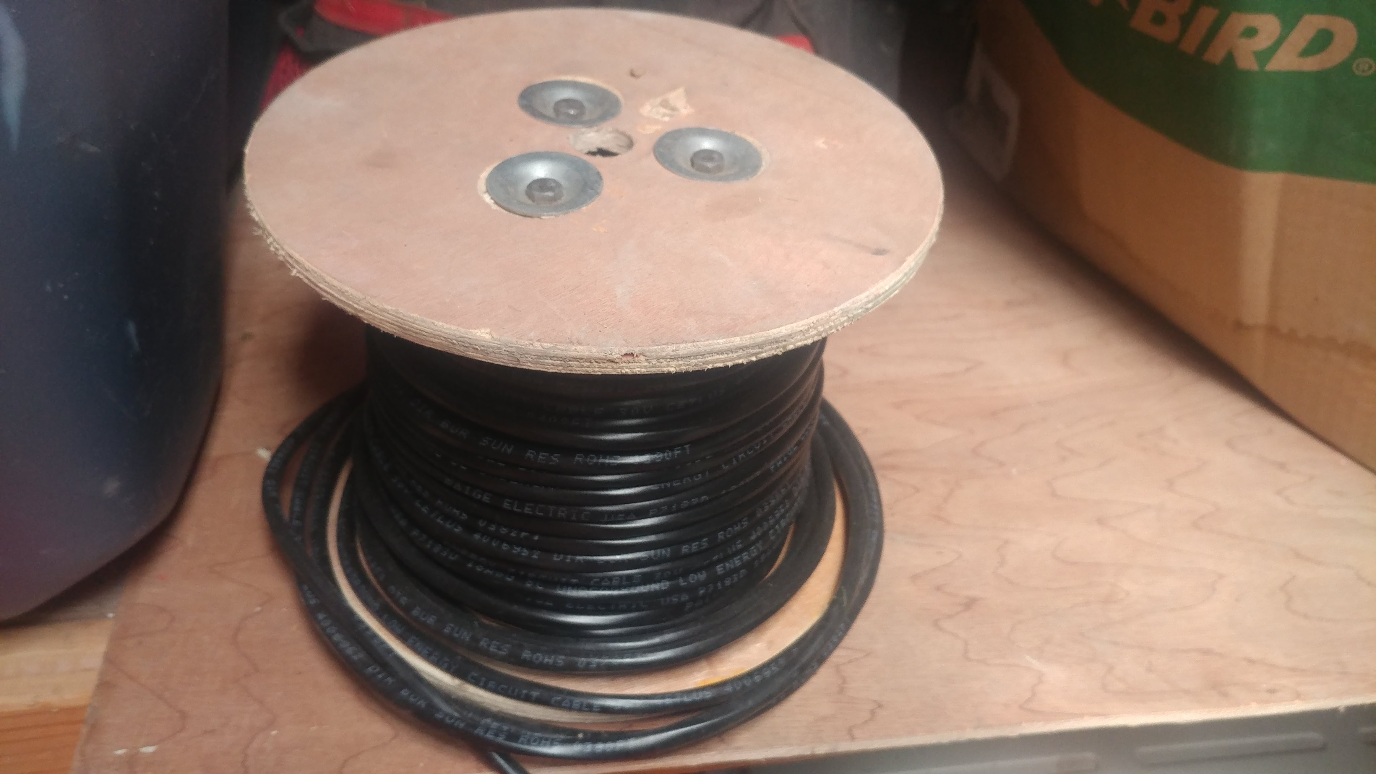
Sprinkler Valve Wiring doesn’t need to be a headache if you just apply some logic. For starters, always use an approved direct bury wire that is designed for sprinkler systems. Several times a year I come across sprinkler valves that have been wired with everything from 12 gauge Romex to 26 gauge Cat 5 wire. While the 12 gauge Romex could arguably be acceptable(even though it is over kill) the 26 gauge Cat 5 wiring is not acceptable in any conceivable way. Keep in mind that if you are using a wire that is not rated for direct burial it is unlikely to hold up more than a year or 2. This was the case for the customer that called me with a complaint that her valves would “sometimes work and sometimes not” after seeing that the previous owner had wired the valves with Cat 5 wire, I told her that the only way to fix the problem was to install a new run of wire from her garage all the way to the front of her property, we will just say she was not a happy camper. After materials and labor it cost her approximately $700.00 simply because the previous homeowner chose not to use the proper wire. It would have cost the previous homeowner about $35.00 to use the correct wire.
Color Coded Wire
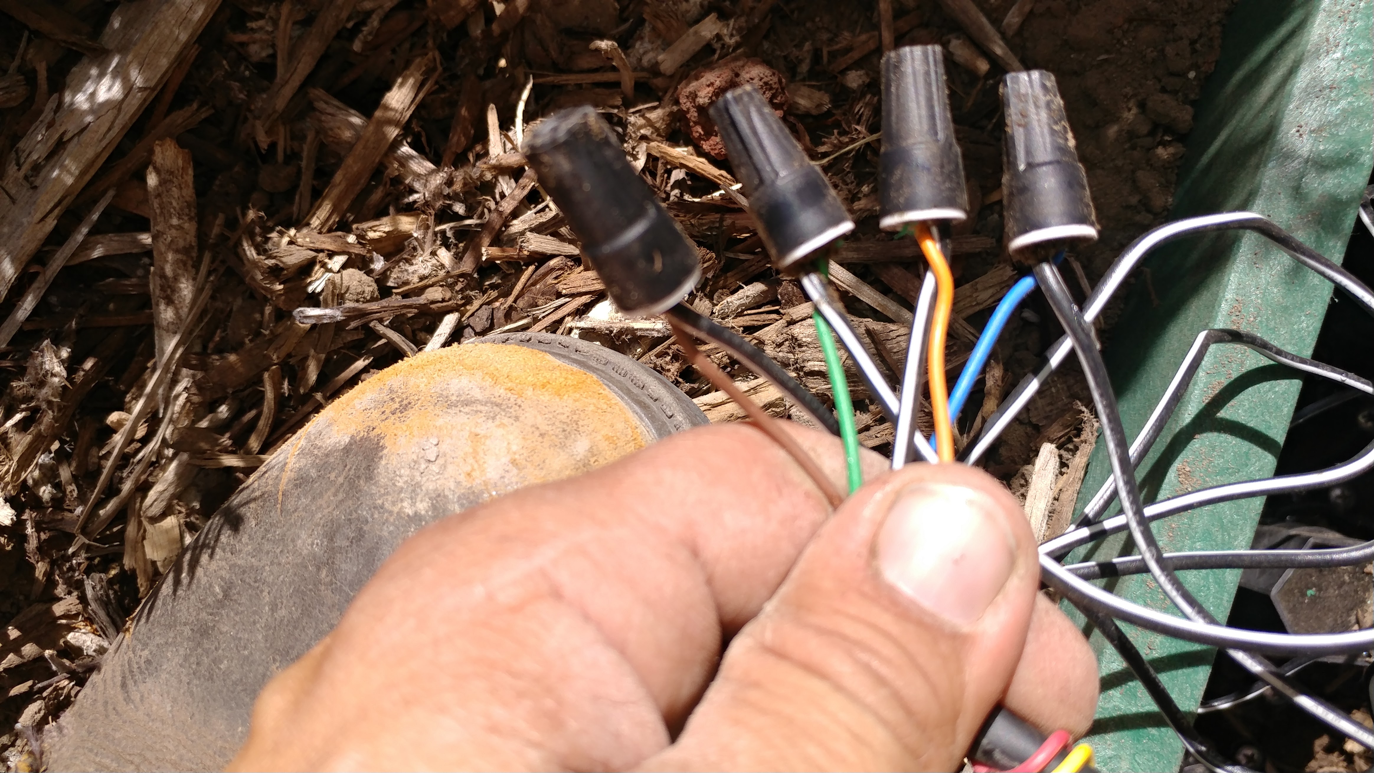
The colors of the individual wiring is not just to make it look good, the colored wiring is intended to help distinguish zones from the valve all the way to the clock. While there isn’t any real color code to follow, it is wise to stick to a pattern. For instance, the common (negative) wire is generally White, while the first zone is generally Red. I always take a picture in the field as a reference. That is where this photo came from. This particular one is a repair, so the color code wont match my regular example.
My Color Code Example
- Red
- Yellow
- Blue
- Green
- Orange
- Purple
- Gray
- Black
- Pink
Check out the Install Examples
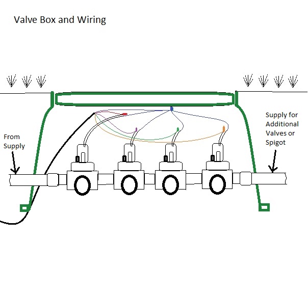
Wiring Valves
When I wire Valves, I always start by selecting one wire from each valve and connecting them to the common (there are 2 wires coming out of each valve solenoid, as these wires are connected to a coil/electromagnet, the polarity doesn’t matter, so simply select a wire for the common and the other will be used to control the valve). Once you have the common connected, you will have one wire left for each valve. Simply connect a different color wire to each valve. Follow the color code example if it makes it easier to understand.
Grease Packs or Grease Nuts
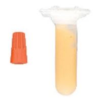
Grease packs are arguably more effective, but grease nuts are more common. They both provide a great line of defense against moisture. The grease packs are probably superior, but they are more expensive. I generally use grease nuts, but I will use grease packs if there is a likely hood of wires being submerged in water for an extended periods of time, or if the installation is on a commercial property
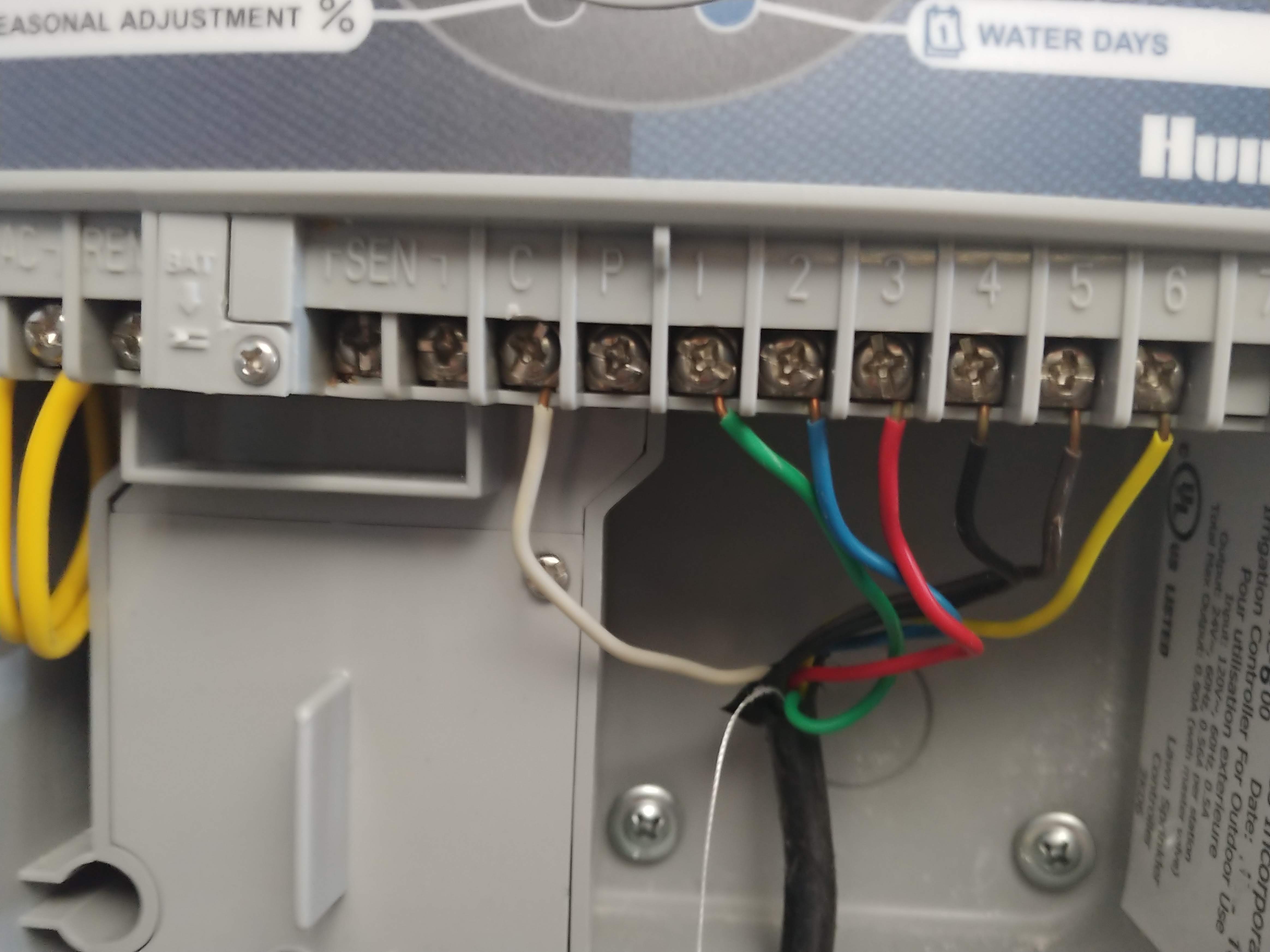
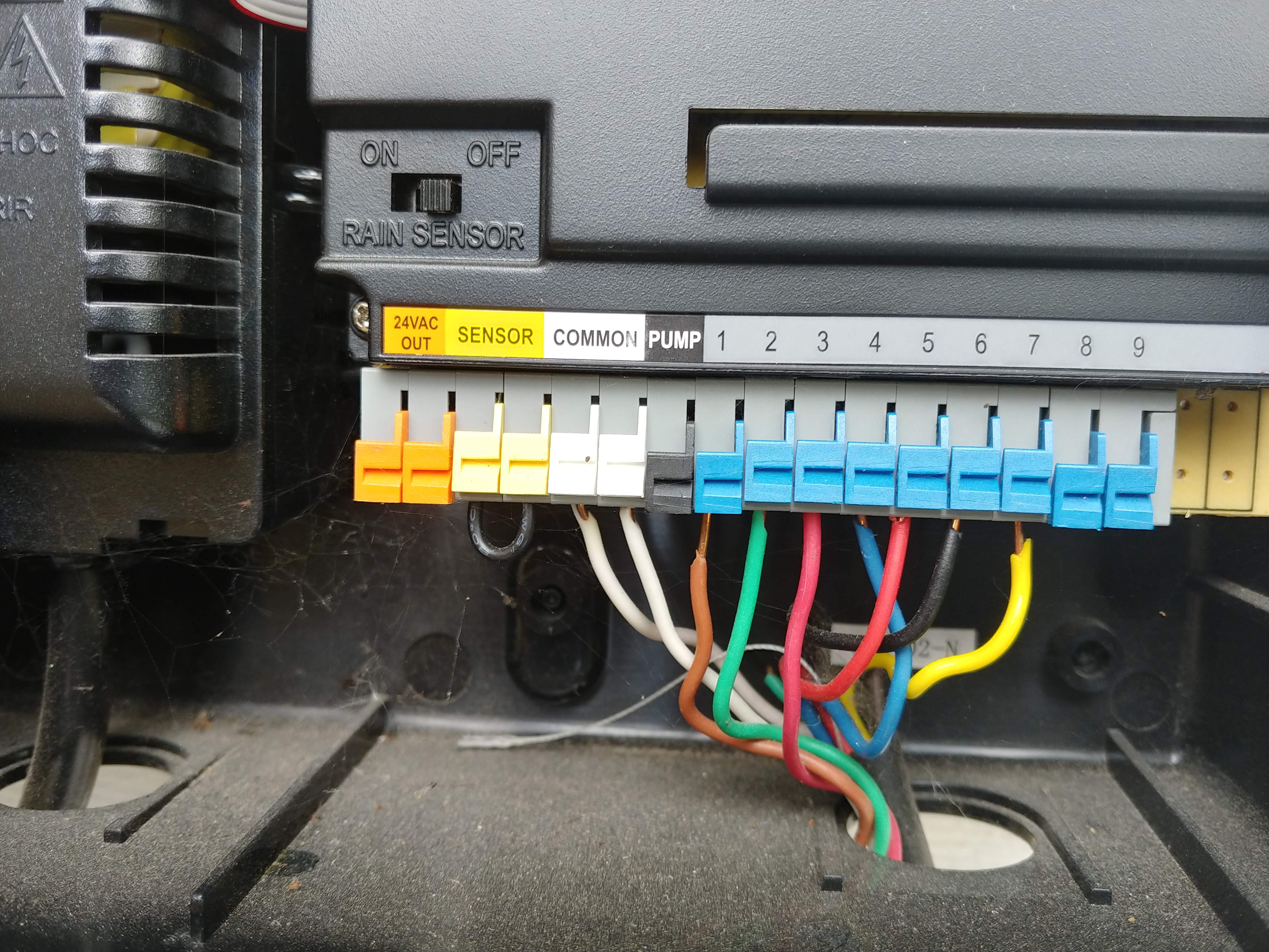
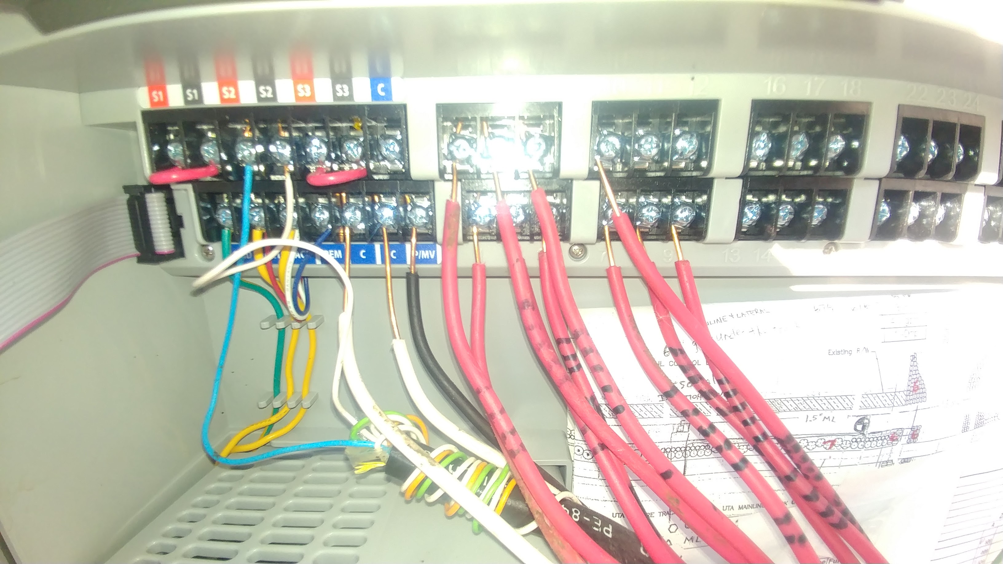
Wiring Timer / Sprinkler Clock
Wiring a Timer / Sprinkler Clock is actually very simple, you simply connect the wire that is used as the common (-) to the “Com”, “C” or “Common” slot/port/screw and you connect the colored wires to the corresponding zone number slot/port/screw. See the Images for a better example. These are not the best examples, but they are the only pictures I have at the moment.
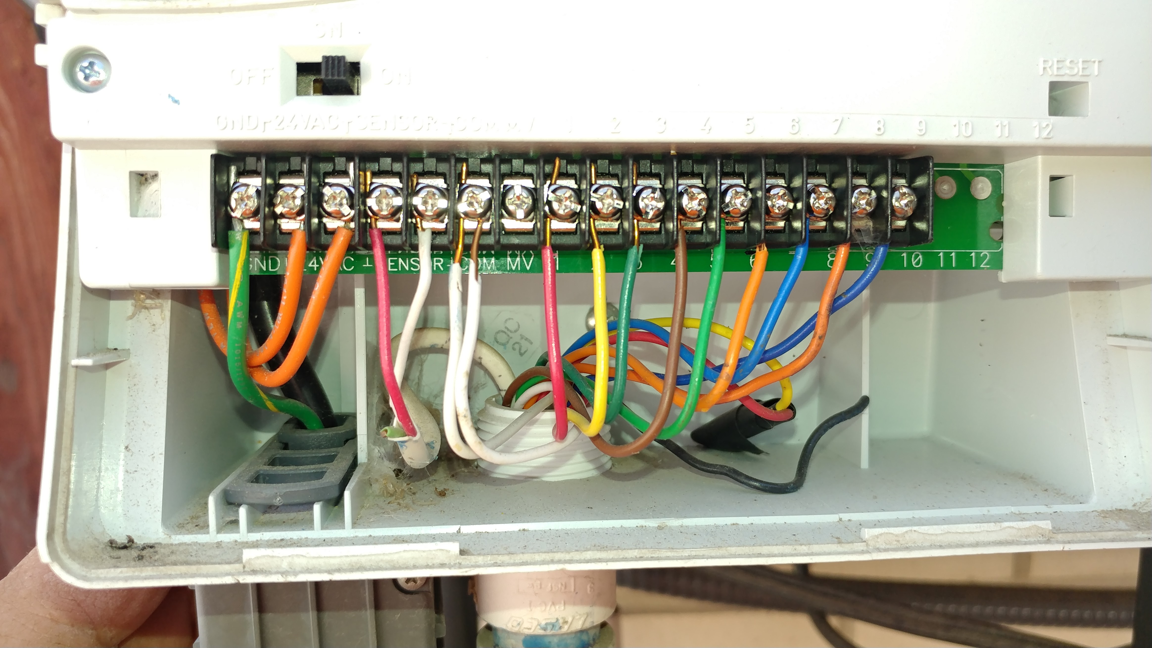
This as a commercial clock that was poorly installed, causing the system to short out whenever the wires were bumped.